One of the most attractive properties of a Finite Impulse Response (FIR) filter is that a linear phase response is easier to achieve. Not all FIR filters have linear phase though. This is only possible when the coefficients or taps of the filter are symmetric or anti-symmetric around a point.
Today I want to describe the reason behind this kind of phase response in an intuitive manner. We have described Finite Impulse Response (FIR) filters before. Moreover, we have also discussed that the Discrete Fourier Transform (DFT) of a signal is complex in general and therefore both magnitude and phase plots come into the picture.
Why is Linear Phase Important?
To understand its significance, consider a filter with a unit magnitude response and a linear phase response, where $t_0$ is a constant.
\[
H(\omega) = e^{-j\omega t_0}
\]
This phase response $\theta=-\omega t_0$ is linear as it is similar to the linear equation $y=mx$ where the slope $m$ is given by $-t_0$.
- In time domain, the output $y(t)$ is a convolution between the input signal $x(t)$ and the impulse response $h(t)$ of this filter.
\[
y(t) = x(t) * h(t)
\] - In frequency domain, the output $Y(\omega)$ is a product between the input spectrum $X(\omega)$ and filter response $H(\omega)$.
\[
Y(\omega) = X(\omega)\cdot H(\omega)
\]
With $H(\omega)$ as given above, and taking its inverse Fourier Transform, we get
\[
y(t) = \int _{-\infty}^{\infty} Y(\omega)e^{j\omega t}d\omega = \int _{-\infty}^{\infty} X(\omega)e^{-j\omega t_o}e^{j\omega t}d\omega
\]
This can be simplified as
\[
y(t) = \int _{-\infty}^{\infty} X(\omega)e^{j\omega (t-t_0)}d\omega = x(t-t_0)
\]
In words, the linear phase property of a filter delays the input signal $x(t)$ but preserves the signal shape with no distortion. This is the main reason behind why DSP engineers prefer a linear phase response in most (but not all) signal processing applications.
An FIR Filter
Based on whether the filter length is even or odd, and the filter taps are symmetric or anti-symmetric, there are 4 types of FIR filters. Our focus is on the simplest case: an odd length filter (so that the taps are symmetric around a single point) with symmetric coefficients.
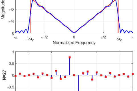
Shown below in the figure is an odd-length FIR filter with symmetric coefficients. The corresponding magnitude response is also plotted below.

To understand the idea, let us consider only the two samples at times $n=+1$ and $n=-1$. Imagine that the remaining samples have disappeared and whatever conclusion we draw for the samples at $n=\pm 1$ can also be applied to them.
An Impulse in Time
What does a time domain impulse correspond to in frequency domain? To answer this question, we refer to the definition of the Discrete-Time Fourier Transform (DFTF).
\[
X(e^{j\omega})=\sum_{n=0}^{N-1} x[n]e^{-j\omega n}
\]
Clearly, when the input $x[n]$ is an impulse at $n=+1$, we have
\[
X(e^{j\omega})=\sum_{n=0}^{N-1} \delta [n-1]e^{-j\omega n} = e^{-j\omega \cdot 1}
\]
The result is a complex sinusoid in frequency domain with period 1! Another way of seeing this ideas is as follows.
From the concept of frequency, we know that a complex sinusoid in time domain corresponds to an impulse in frequency domain. Owing to the time-frequency duality, an impulse in time domain corresponds to a complex sinusoid in frequency domain!
But we have two impulses in terms of two filter coefficients at $n=\pm 1$.
From One to Two Impulses
Two impulses at $n=\pm 1$ imply two complex sinusoids rotating in frequency domain in opposite directions. The result is that the frequency domain signal can be written as
\begin{equation}\label{equation-cosine-1}
e^{+j\omega\cdot 1}+e^{-j\omega\cdot 1} = 2\cos \left(\omega \cdot 1\right)
\end{equation}
where we have used the Euler’s identity to simplify the above expression. Observe that the above signal is not a time domain cosine; instead, it is a frequency domain sinusoid.
Symmetric Coefficients
With this background, symmetric coefficients of an FIR filter $h[n]$ come into play. For an $N$-length filter due to symmetry, we have
\[
\begin{aligned}
h[0] &= h[N-1] \\
h[1] &= h[N-2] \\
\vdots &= \vdots\\
\end{aligned}
\]
Since DTFT is given by $H(e^{j\omega})=\sum_{n=0}^{N-1} h[n]e^{-j\omega n}$, the contribution from these two terms can be written as
\[
h[0]e^{-j\omega\cdot 0} + h[N-1]e^{-j\omega(N-1)}
\]
This expression can be simplified using the following two facts.
- $N$ is odd, so $N-1$ is an even number.
- The coefficients $h[0]$ and $h[N-1]$ are the same.
Thus, we can write
\[
\begin{aligned}
h[0]e^{-j\omega\cdot 0} + h[0]e^{-j\omega(N-1)} &= e^{-j\omega\cdot \frac{N-1}{2}} h[0]\Big[e^{+j\omega\cdot \frac{N-1}{2}} + e^{-j\omega\cdot \frac{N-1}{2}}\Big]\\
&= e^{-j\omega\cdot \frac{N-1}{2}} \underbrace{ h[0]\cdot 2\cos \left(\omega \frac{N-1}{2}\right)}_{\text{Real frequency domain signal}}
\end{aligned}
\]
where we have used the Euler’s identity for cosine above. The real signal has no imaginary component and hence a zero phase. All that is left in the phase part is the following term.
\[
\text{Phase response} = -\omega\cdot \frac{N-1}{2}
\]
which is clearly a linear expression similar to $y=mx$. The x-axis represents $\omega$ while the slope is given by $-(N-1)/2$.
Conclusion
In the above equation, we have only considered the contributions from impulses at $n=\pm 1$. The impulses or coefficients at other times also add up to real cosines with similar phase contributions as above, i.e., $(N-1)/2$.
This is why it is straightforward to design an FIR filter with linear phase response by simply choosing symmetric or anti-symmetric coefficients. This is not the end of the filter design story though. IIR filters have certain advantages over FIR filters in some other respects.