The radio spectrum is a very precious resource like real estate and must be utilized judiciously. Pulse shaping filters control the spectral leakage of the transmitted signal in a wireless channel due to the strict restrictions to comply with a spectral mask. This is even more important for the upcoming 5G wireless systems which are based on a variety of wireless transmission protocols (such as mobile networks, Internet of Things (IoT) and machine to machine communications) combined in one comprehensive standard. Even for wired channels, there is always a natural bandwidth of the medium (copper wire, coaxial cable, optical fiber) that imposes upper limits on its utilization.
Background
The design of a good pulse shaping filter starts with the smallest possible bandwidth exhibited by a rectangular spectrum. However, that abrupt transition in the frequency domain gives rise to long tails in the time domain. To avoid this problem, a smoother rolloff $\alpha$ of the spectrum is desired for which we can extend the bandwidth in any shape as long as it has odd symmetry around half the symbol rate $\pm 1/2T_M$ to satisfy Nyquist no-ISI (Inter-Symbol Interference) criterion, where $T_M$ is the symbol time. This extension can be logically conceived as a convolution between the rectangular mass of width $1/T_M$ and an even symmetric taper of width $\alpha/T_M$ where $0 < \alpha \le 1$. This even symmetry preserves the odd symmetry around $\pm 1/2T_M$ in the resultant filter.
Drawbacks of Raised Cosine
The smoothest spectral shape one can imagine is a sine or cosine. A half-cosine of width $\alpha/T_M$ — an even symmetric shape — is convolved in frequency domain with a rectangular spectrum to generate the most commonly used pulse known as a Raised Cosine (RC) filter. The parameter $\alpha$ is the excess bandwidth or rolloff factor in the resultant desired spectrum.
Since the convolution in time domain is multiplication in frequency domain, an RC filter is divided into two parts in frequency domain: one at the Tx and one at the Rx, both of which are square-root of the original RC filter and are known as Square-Root Raised Cosine (SRRC) filters. The Tx SRRC filter implements the shaping filter that determines the spectral mask while the Rx SRRC filter implements the matched filter that maximizes the SNR at the Rx.
The Raised Cosine concept is a good starting point for pulse shape design and its closed-form mathematical expression is good for analytical purpose. Nevertheless, there are two major drawbacks in using an SRRC pulse for shaping the spectrum.
- Since the transition band of an RC pulse is half cycle of a cosine, the transition band of an SRRC pulse is a quarter cycle of a cosine. Its abrupt termination at the stopband results in a discontinuity causing a limit to the sidelobe (SL) suppression that an SRRC pulse can achieve.
- As a consequence of truncation in time domain, the pulse is no more absolutely band-limited within $(1+\alpha)/2T_M$ and assumes infinite support in frequency in the form of sidelobes. This is because the truncation in time domain (i.e., multiplication by a rectangular window) causes subsequent convolution in frequency domain between the SRRC spectrum and a sinc signal. This operation moves the half amplitude values away from the odd symmetry points of $F = \pm 1/2T_M$ violating the Nyquist no-ISI criterion and inducing increased ISI.
This leads us to other pulse shape design procedures that produce a Nyquist filter with improved stopband attenuation preferably without any degradation in peak ISI. We discuss two main design techniques for finding a superior pulse shaping filter: transformation of a lowpass filter based on Parks-McClellan algorithm to a Nyquist filter, and convolution of a frequency domain window with a rectangular spectrum.
Transformed Lowpass Filter
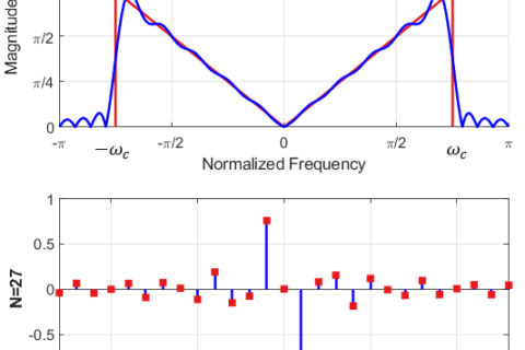
The standard method is by starting with an initial lowpass filter that is designed according to the Parks-McClellan algorithm whose passband and stopband edges are matched to the rolloff boundaries of the Nyquist spectrum. The Parks-McClellan algorithm is an iterative algorithm for finding the optimal FIR filter based on Remez exchange algorithm and Chebyshev approximation theory such that the maximum error between the desired and the actual frequency response is minimized. Filters designed this way exhibit an equiripple behavior in their frequency responses and thus are also known as equiripple filters, where equiripple implies equal ripple within the passband and the stopband that are not necessarily the same (in fact, mostly they are not).
Naturally, this lowpass filter crosses the band edge $F = 1/2T_M$ with more attenuation than $-3$ dB level required for a Nyquist spectrum. Since the transition band belongs to the filter designer, the passband edge frequency can be pushed forward towards $-3$ dB level. This can be implemented in a software routine through a few iterations of increasing the passband edge frequency based on a gradient descent method, just like an offline adaptive filter.
For a sampling rate $F_S$, passband frequency $F_{\text{pass}}$, stopband frequency $F_{\text{stop}}$ and a positive constant $\mu$ that controls the rate of convergence and the approximation error, the procedure in the $n$-th iteration is listed below:
- design a lowpass filter using Parks-McClellan algorithm with frequency set $\big\{0~~ F_{\text{pass}}[n] ~~F_{\text{stop}}~~ F_S/2\big\}$,
- find the error between $-3$ dB and the filter attenuation in dB at $1/2T_M$ as
\begin{equation*}
e[n] = -3 ~- P_{\text{dB}}(1/2T_M),
\end{equation*} - update the passband frequency as
\begin{equation*}
F_{\text{pass}}[n+1] = (1+\mu e[n])F_{\text{pass}}[n]
\end{equation*}
For most cases, a few iterations are enough for transforming it into a Nyquist filter. There is a weighting option available as well that can place more emphasis on a desired frequency band at the expense of the remaining bands. For example, more stopband attenuation can be achieved by weighting it at a cost of increased in-band ripple.
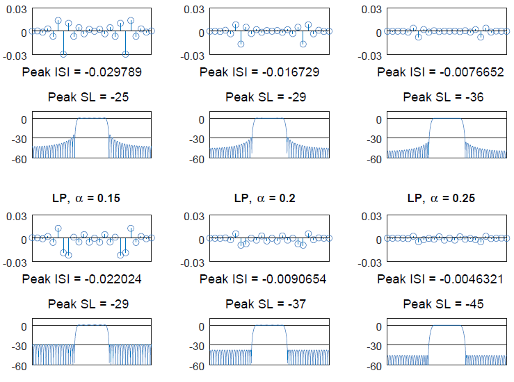
For a better visual understanding, we create a length $49$ square-root Nyquist filter using a transformed lowpass filter with three different excess bandwidths, namely $\alpha = $ $[0.15,~0.2,~0.25]$ and a group delay equal to $6$. Next, their frequency response is plotted along with the measure of sidelobe attenuation. Finally, two square-root Nyquist filters are convolved and downsampled at $1$ sample/symbol to observe the respect peak ISI levels. The results are drawn in Figure below.
Window Based Filter
The other procedure, devised by fred harris, is based on the convolution of a smooth taper of width $\alpha/T_M$ with a rectangular spectrum of width $1/T_M$. To affect maximum smoothness, this taper should simply be a good spectral window with a narrow mainlobe width and low sidelobe levels. One such candidate is a Kaiser window which is an approximation to the prolate-spheroidal window for which the ratio of the mainlobe energy to the sidelobe energy is maximized. Given a fixed length, a parameter $\beta$ controls the sidelobe height which decreases with $\beta$ at a cost of increase in the mainlobe width. The coefficients for Kaiser window $w(n)$ are given by
\begin{equation*}
w(n) = \begin{cases}
\frac{I_0 \left(\pi \beta \sqrt{1-\left(\frac{n}{N/2}\right)^2} \right)}{I_0(\pi\beta)} & -N \le n \le +N \\
0 & ~~\text{otherwise}
\end{cases}
\end{equation*}
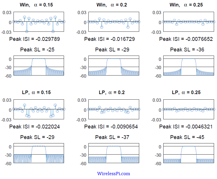
where $I_0(\cdot)$ is the zero-order modified Bessel function of the first kind. Again, we create a length $49$ square-root Nyquist filter using a frequency domain window based filter with similar excess bandwidths $\alpha = $ $[0.15,~0.2,~0.25]$, $\beta=12$ and a group delay of $6$. Next, their frequency response is plotted along with the measure of sidelobe attenuation. Finally, two square-root Nyquist filters are convolved and downsampled at $1$ sample/symbol to observe the respect peak ISI levels. The results are drawn in Figure above and compared with the lowpass based design.
Since Parks-McClellan algorithm minimizes the error in the pass and stop bands, it generates optimal filter coefficients and has consequently become the standard method in FIR filter design. Moreover, the iterative lowpass process is more flexible because any sidelobe level can be exchanged with the in-band ripple by utilizing the penalty weights. On the other hand, the Kaiser window technique is not as flexible. Due to the convolution of the spectra, the stopband ripple and the in-band ripple are always the same amplitude.
The figure above demonstrates in each case that the sidelobe attenuations exhibited by the lowpass filter are significantly better than the window based filter, along with its peak ISI being either comparable or even better, so the lowpass filter design is overall a superior scheme. Howover, window based technique is superior in terms of peak ISI in some settings. There is room for choosing one over another depending on the system requirements.
Hello Qasim, Thanks for your tutorials. They are really great and explains the concept with little math. I just ordered your book to study.
I have a question on samples/symbols if you don’t mind me asking it. Consider the QPSK modulation system (just an example). I have digital binary data 101101101001000 … which needs to be modulated using QPSK and RRC filter for pulse shaping.
Once bits are converted to symbols : {-1+i,-1-i,1+i,1-i…} we mutiply with pulse shaping function which is RRC .
When I work with real hardware , I always finds something like samples/symbols.. What exactly is this term … Is it no of samples required to represent a RRC Pulse ??
Eventually -1+i is going to convolved with a digitized RRC pulse (2 samples if we say 2 samples/1 symbol or 4 samples if we says 4 samples/1 symbol.) Am i thinking in a right way??
If this is true , how can a RRC pulse be represented using just 2 or 4 samples ?? are they really enough
Hi Ashish. Excellent question. I hope that you will have found the answer by now after reading the relevant section in my book.
In short, you’re on the right track to which you only need to add the concept of the group delay. An RRC pulse cannot be represented by L=2 or L=4 samples and instead the total length of the pulse is 2*L*G+1 where G is the group delay. It represents the number of symbols to the left and right of the pulse peak (and hence the factor 2 above).
I hope this helps. You can also read a detailed note on https://wirelesspi.com/pulse-shaping-filter/
Hi Qasim,
It is really a nice tuitorial but I am confused about how to work out the ISI of the filter.
There can be different measures but this tutorial describes peak ISI, i.e., the highest amplitude (absolute value) at a non-zero time index.
Dear Qasim,
How you calculated this peak ISI value.I missed that part in the tuitorial.Kindly let me know how you got this peak ISI value from which plot.
There is one figure above that contains the pulse sequence and its spectrum. The ISI should be zero at all non-zero integer multiples of symbol time indices but obviously it is not. Taking the magnitude of the largest such sample from the symbol time indices is peak ISI.
Thanks Qasim ,
I know that from the figure it is calculated but how to get that figure was my question.
The methods are also described in the above post. Basically, you have to design a square-root Nyquist filter and then convolve it with itself to generate a Nyquist filter. Eliminate the sample at time index 0 and what remains on both right and left sides at symbol intervals is the ISI. The one with the highest magnitude then represents the peak ISI.
Thanks Qasim.
It was really helpful.
Hi Qasim !
Really helpful guide ! Could you maybe also provide some links/references to Nyquist pulse shaping filters realizable in analog domain ? For instance a integrate and dump is a realizable filter (its a sinc in frequency domain, impulse response is rect).
Thanks in Advance !
Anirudh, thanks for your kind words. Unfortunately, I am not aware of any good reference for designing Nyquist pulse shaping filters in analog domain. All the best.
Thanks for the response Qasim. Your website really helped me understand the basics in a short time !